
Page 75 - Build 152
P. 75
Technology
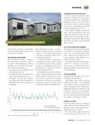
Figure 2: Research facilities at Tamaki Campus, University of Auckland.
Testing facilities at the university
Office-size construction facilities at the University of Auckland were constructed to test the potential bene t of using PCM in buildings (see Figure 2). Two of the o ces were identical, except the interior gypsum board in one was impregnated with PCM that had a melting point of 18–22°C.
Solar radiation, humidity and ambient indoor and wall temperatures have been continuously monitored for the two o ces during the last 7 years. Each o ce also has a heat pump for heating and cooling, providing information on annual energy savings with the use of PCM.
Tests show temperature damping
Typical measurements generated from the test facilities show significant damping e ects to the interior temperature in the office with PCM. This utilises the free cooling available at night, which is used to solidify the PCM (see Figure 3).
The daytime temperature of the PCM o ce is about 5°C cooler than the other o ce, except when the ambient temperature during the night before was not low enough to solidify the PCM.
Peak load shifting
Applying PCM in buildings can also create electricity peak load shifting.
When PCM is used in a home’s walls and ceilings, the heating or air conditioning can be switched o for an extended period without changing the indoor temperature signi cantly. This means electricity use could be limited to low-peak periods, helping to level the electricity peak load. If variable price-based electricity is provided, this will also translate to electricity cost saving.
Savings on cooling
In another study, cooling by ventilating at night combined with PCM-impregnated gypsum boards was experimentally inves- tigated using the same facilities.
The two test o ces equipped with smart control systems were used to test the
with PCM. The shaded area is the melting range of the PCM in which energy is stored as a latent heat of melting.
Improving by encapsulating
Microencapsulation of PCM is a technique that allows PCMs to be durable. Because of the nature of PCMs, bulk usage of PCMs in buildings can be problematic. The advan- tages of microencapsulation are:
● increasing surface area, which gives better heat exchange properties
● protecting the PCM from leaking to the outside environment and vice versa
● allowing the core material to undergo phase change and volume change without a ecting the bulk structure or integrity of the building.
Microcapsules have two parts – a core mate- rial and a shell material. The core material consists of a PCM, and the shell material is usually a cross-linked polymer such as polymethyl methacrylate.
A common PCM that is encapsulated is a para n wax, with a suitable melting point. The two major steps in microcapsule formation are emulsi cation and the poly- merisation process. Both have an e ect on the microcapsules produced.
It is desirable to produce spherical micro- capsules containing a high proportion of PCM and low polymer concentrations to enable the product to retain most of its thermal characteristics. Details of the encapsulation technology developed at the University of Auckland are available in published reports.
35 30 25 20 15 10
5
0
Hut 1 inside temperature
Hut 2 (with PCM) inside temperature
0 24 48 72 96 120 144 168 192 216 240 264 288 312 Time (hr)
Figure 3: Measured indoor room temperatures during summer.
Build 152 — February/March 2016 — 73
FEATURE SECTION
Temperature (°C)
