
Page 31 - Build 152
P. 31
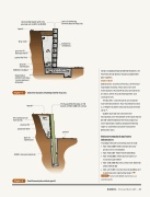
concrete blockwork with fully grouted cells to NZS 4210:2001
topsoil
 lter cloth
granular  ll drainage metal
geotextile  lter
drain to stormwater
100 mm turndown
longitudinal reinforcing in base (as per engineers drawings)
vertical reinforcing
60 mm cover to  lled side
horizontal reinforcing
Figure 7
H4 treated rails or half rounds
granular  ll geotextile  lter
drain to stormwater
20 MPa concrete minimum
tongue and groove boards behind the poles (see Figure 8). Design details may be available from pole suppliers.
Gabion wall
Gabion walls also rely on the mass of the wall to provide retaining. They consist of steel mesh baskets, filled with locally sourced rocks or stones, which may be tied together and stacked in tiers.
The baskets can be made to any shape or wall configuration but they should not exceed a 2:1 height to width ratio and may be inclined upto7°.
Gabion walls do not need concrete foundations, but the bottom of the wall should be 150–200 mm below the finished ground level to provide stability. Geogrid reinforcing fabric is sometimes buried in the backfill behind the wall.
Relevant standards and extra information
Standards relevant to retaining walls include:
● NZS 3602:2003 Timber and wood-based
products for use in building
● NZS 3604:2011 Timber-framed buildings
● NZS 3640:2003 Chemical preservation of
round and sawn timber
● NZS 4210:2001 Masonry construction: Materials
and workmanship
● NZS 4229:2013 Concrete masonry buildings not
requiring speci c engineering design.
For more Refer to BRANZ Bulletin 562 Low retaining walls.
Concrete masonry retaining wall for clay soil.
topsoil
H5 treated 150 mm pole at 1:10 batter at 900–1200 mm centres
ground
Figure 8
Cantilevered pole retaining wall.
Build 152 — February/March 2016 — 29
